Block diagram of 16:1 mux using four 4:1 mux only – valuable tech notes Internal circuit of mux 8 to 1 mux circuit diagram
Combinational Circuits - MUX Part 7 - YouTube
Combinational circuit: mux and de-mux
[diagram] 8 1 mux logic diagram
8 1 mux truth tableImplementing 2:1 mux with 4:1 mux in combinational logic circuit Innovative blood: multiplexers2 to 1 mux circuit.
8 to 1 multiplexer circuit diagram16:1 mux : vlsi n eda Learn 8 to 1 mux using 4 to 1 mux by two different methodsMultiplexer pos slideserve map ppt powerpoint presentation.
What is enable in multiplexer
Multiplexer demultiplexer mux circuit difference demux between signals input output provide control single orderMux schematic diagram 8x1 mux multiplexer 4x1 logic implementation implement multiplexers logical 2x1Combinational and sequential design of a 4-bit adder. (a) ha circuit.
Multiplexer mux solving geeksforgeeks explanationVerilog code for 2:1 multiplexer (mux) Is mux a combinational circuit2:1 mux using cmos logic only..

8x1 mux logic diagram : using 8 1 multiplexers to implement logical
What is a mux circuitCombinational circuits 4 to 1 multiplexer circuit diagram and truth table2x1 mux using half adder.
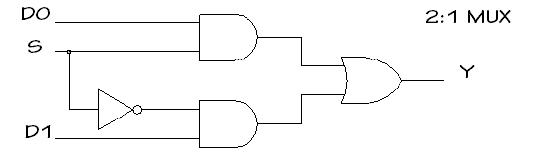
Developed 8 to 1 multiplexer diagram and truth table2 1 mux circuit diagram with truth table wiring diagr 2 1 mux circuit diagramDifference between multiplexer and demultiplexer (with operational.

Solved we can also use the multiplexer circuit to implement
Multiplexer inputsMux multiplexer logic verilog 2x1 circuit Circuit mux circuitlab descriptionMultiplexer mux circuit diagram truth electronics inputs nand gates multiplexing combination boolean given elcho.
Mux circuit innovative blood multiplexersAdder sequential combinational circuits compressed garbled scalable highly Solving multiplexer circuitAppel wiring diagram nmax, wiring manual pdf: 18 5 wiring diagram garmin.

Solved 10 combinational logic circuit design with
4 to 1 mux circuit diagram .
.


